
ADVANCED PROCEDURES
The topics presented on this web page are those procedures used infrequently or for servicing unusual issues.
Throttle shaft bushing replacement
The IDA3C (3 Choke) carburetor was developed from the two choke IDA Weber carburetor. One of the differences between these two designs is the deletion of the ball bearings used to support the outer ends of the throttle shaft as utilized in the two-barrel IDA carburetor. This detail design change has the IDA3C throttle shafts in direct contact with the throttle body; wearing both the shafts and the journal bearings in the throttle body. Over time this wearing creates clearances allowing uncontrolled air into the fuel/air mixture delivered to your engine. Erratic idling, "sniffing" through the intakes, ticking noises heard at idle or popping from the exhaust are symptoms of this wear issue.
Most of the triple throat carburetors used in the Porsche world have 40mm bore sizes. A smaller number have 46mm bore sizes, the earliest versions were dedicated for race applications and in later years the 46mm bore Webers were used for large displacement street engines. Both of these bore diameter configurations were created on the same basic throttle housing which means the bearing journal lengths supporting the throttle shafts for the 46mm bores were 3mm shorter for each journal. In addition to the shorter length of the journal bearings the larger throttle plates created more load for the journals to support. When the numbers are calculated the bearing load for 46mm bores is found to be 64% greater than those journal loads for 40mm bores. Obviously the bearing life for the larger bore Webers is shortened in comparison to the 40mm bore carburetors.
The earliest triple throat Webers used plain bearings to support the throttle shafts at the six journals in each throttle body but a design change in 1967 incorporated Teflon strips to act as bearings. These strips were rolled into a tube and used as bearings in the outer two journals of the throttle bodies. These Teflon bearings actually accelerated shaft and journal wear issues since Teflon easily displaces under running loads and thereby allows the throttle shaft to rapidly wear with the remaining support area with the throttle body.
Keeping carburetors in service with throttle shaft and journal clearance issues eventually causes additional throttle shaft and journal wear at the next set of bearings inboard from the outer bearings. When this occurs it usually will require throttle shaft replacement and a comprehensive bearing service to return the Webers to proper performance.
There are those who replace these Teflon bearings as the solution for throttle shaft and journal wear issues but this solution is short lived, the Teflon will rapidly yield, returning your throttle shaft fit to nearly the same as before the repair, rendering the repair as ineffective. The recommended repair is to replace the worn bearings with new equivalent bearings, the good news is that the portion of the throttle shaft under the Teflon "bearing" is typically suitable for reuse.
Throttle shaft bushing wear is the fundamental reason why these Weber carburetors become erratic performers and are difficult to tune and to stay in tune. Several paths are available for repair of these bushings:
Bushing replacement with two OEM Teflon bearings
A simple, replacement repair with very short duration life
Repair method not applicable for throttle housings pre-dating their use
Air leakage past worn throttle shaft and elongated journal may create idling air flow balancing issues
Inner four bearing journals left unserviced
Bushing replacement with two bronze bearings
A bushing with its length matching that of the OEM Teflon bearings is used
Not a simple replacement repair for throttle housings pre-dating use of Teflon bearings
Air leakage past worn throttle shaft and elongated journal may create idling air flow balancing issues
Inner four bearing journals left unserviced
Bushing replacement of all six bearings supporting throttle shafts
Six, full length bronze bearings installed into each throttle housing
Throttle shaft axis align-bored to receive throttle shafts
Throttle bores re-sized to trim ends of bushings after installation
New throttle valves machined to match the resized throttle bores
Premium repair method; throttle bearings upgraded to better than OEM specifications
Repair method adopted by Performance Oriented
The replacement of the Teflon "bearings" is a task a skilled technician may accomplish but the effort requires a deep skill set to remove and reinstall the throttle valves and their fasteners. The tasks identified where metallic bushings are installed requires specialized tooling and machinery so these are best left to specialized service providers.

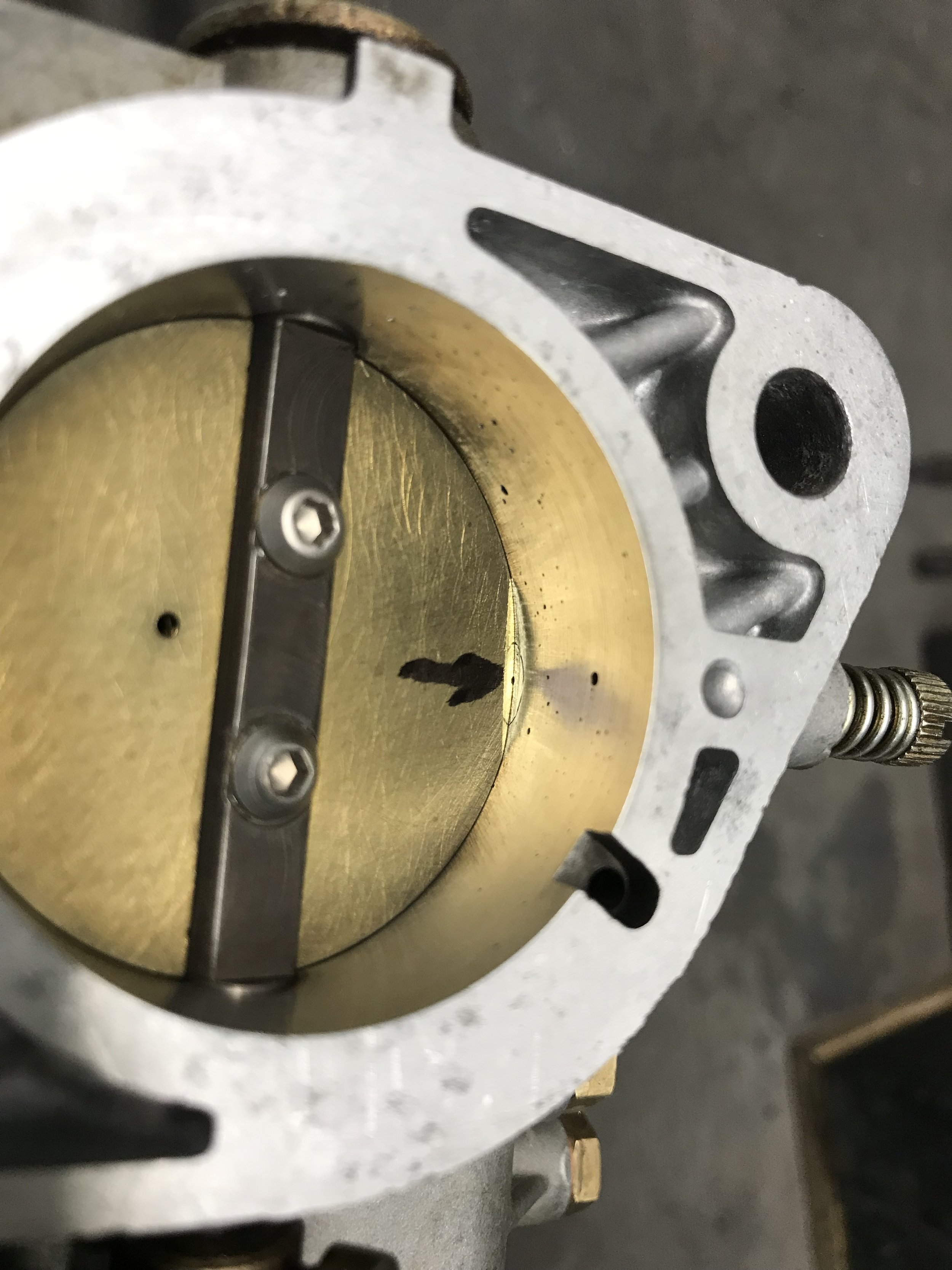
The Teflon bushing (white sleeve on throttle shaft) is installed into the stepped bore in the end of the throttle housing. The bushing is soft and will deform over time allowing the throttle shaft to come into contact with the throttle housing where the Teflon bushing does not extend. This metal-to-metal contact will, over time grind a groove into the throttle shaft which is identified by the pointer.

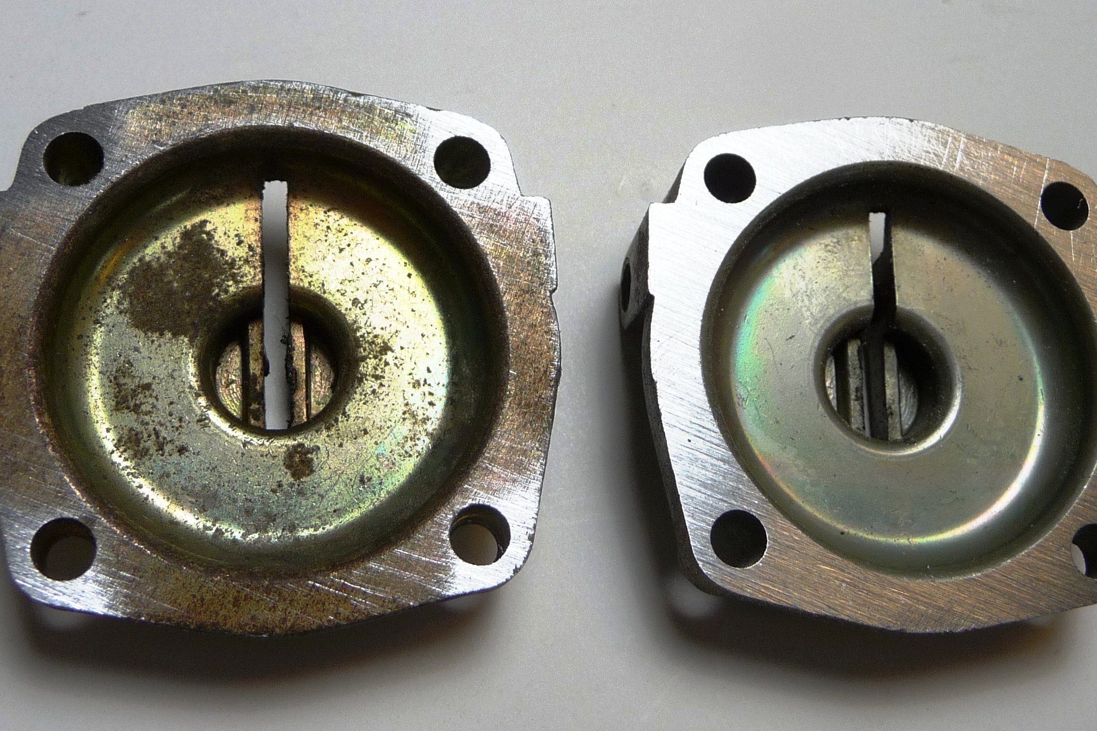
Another image of worn throttle shafts. The long shaft is most commonly worn due to the loading of the throttle return spring however, the short shaft may also be worn as shown.
Throttle Valve Replacement
Edge wear of the throttle valves allows large amounts of air to bypass during idling operation resulting in idle speeds that are too high and cannot be adjusted down. Edge wear of the throttle valves is directly resultant from axial movement of the throttle shafts allowing the throttle valves to rub with the bores in the throttle bodies at nearly closed throttle positions. Uncontrolled axial movement of the throttle shafts contributes to the seemingly random variations in idle and progression operation, as the shaft moves axially, the throttle valves change their clearances with their respective throttle bores which upsets the air being drawn into the engine resulting in erratic engine idling and progression circuit performance.
The idle air adjustment screws provide some compensation for the throttle valve with bore clearance problem but this is a solution that works only at the time of tuning and will not compensate for variations of shaft movement during driving operation.
Replacing worn throttle valves with new equivalents will help reestablish OEM clearances for improved low speed performance. The process sounds easy but can be difficult to achieve since the original shafts must be removed without damaging them and then reinstalled and aligned. Particularly challenging is the removal of the pinch screws securing the throttle valves, their threads are typically rusted or seized with the shafts and they are also mechanically "staked" in place. Also, screwdrivers tend to bugger the screw slots during removal attempts and pressure exerted to keep the screwdrivers from "camming" out of engagement will result in bent throttle shafts. End play must be set correctly to prevent seizing due to thermal expansion differences between the aluminum throttle housings and the steel throttle shafts and to also control excessive lateral movement. Also important to adjust correctly is the "timing" of all three throttle valves so they are matched for air flow at idle position and remain synchronized for larger throttle openings.
Although it is possible for throttle valves to be replaced by a skilled technician it is recommended to let a specialist perform the requisite tasks.

Edge wear of throttle valve. The small protrusion is the unworn edge which was installed in the throttle shaft.

Carbon deposits indicating area of air leakage due to throttle valve and throttle shaft wear.
Vent Pipe Replacement
The top covers of the Weber throttle bodies have two vent pipes installed. They are 8mm in diameter and provide ventilation of the fuel bowls and to minimize fuel sloshing out of the carburetors. They are installed by mechanically riveting the internal end of the pipe thereby making them a non-serviceable item. Over time the vibration of the engine loosens the fit which leaves these pipes loose and ineffective as a slosh preventative. Time is also unkind to these pipes where they are riveted into the ceilings of the top covers. The float bowls are closed chambers subjected to heating and cooling associated with each time the engine is run and then shut down. The cooling cycle draws ambient air into the fuel well along with water molecules and the heating vaporizes the water. Subsequent cooling condenses the vaporized water on the ceiling of the top cover where it facilitates rusting of the riveted end of the vent pipe. Rust flakes drop directly down into the float bowls where it is drawn into the fuel delivery circuits and blocks jets, most notably the idle jets.
Improving Sealing Efficiency of Air Cleaner Housings
OEM air cleaner housings are made of steel with stamped edges that are intended to make intimate contact with rubber sealing gaskets to prevent air from being drawn into the inner chamber other than through the air filter. In particular are the gasketed interfaces in the oblong lower housings attached to the tops of each carburetor. Non-OEM air cleaners have similar sealing interfaces where long edges of filters are in contact with stamped top and bottom plates.
To help overcome the imperfections in the sealing of these long sealing surfaces it is recommended that they are augmented by application of self-adhering, closed-cell, neoprene, foam weatherstrip which is easily acquired from your local hardware store in the form of window sealing tape.
Measuring Fuel Delivery
Fuel pressure and volume are often assumed to be adequate for your carburetor's operational requirements however they are quite important to assure adequate fuel delivery during all power demands of your engine. It is advisable to test for adequate fuel delivery and pressure during peak power demands to verify there is no deficiency of fuel delivery. The following procedure is a complicated but comprehensive method to check adequacy of fuel pressure AND flow during peak engine operational demand:
Estimate the maximum fuel consumption of your engine by multiplying your engine's peak horsepower by 0.10 which results with fuel demand in gallons per hour
Install a flow control valve into the end of the fuel line connected to one of the inlets to the carburetors and downstream from all fuel pressure regulators and filters and close it.
Install a fuel pressure gauge into the fuel line just before the fuel flow control valve. The pressure gauge needs to be a quality item with a peak pressure range of no more than 10 psi. See Standard Procedures for more information regarding fuel pressure gauges.
Install a shut-off valve downstream from the flow control valve and open it.
Connect a fuel line from the shut-off valve and have it drain into a graduated vessel. This vessel should be placed into a larger catch tank to assure spillage of gas will be contained.
This entire setup should be prepared for and the fuel delivery testing conducted out of doors and with a fire extinguisher near at hand.
Connect a battery charger to the battery to simulate power delivery to the fuel pump during normal engine operation.
Activate the ignition switch to start the fuel pump but do not activate the starter for the engine
Adjust the flow control valve to generate a 3.5 psi pressure reading in the fuel line before the flow control valve; this is important since fuel delivery rate under operational pressure will be less than freely flowing fuel
Close the shut-off valve and prepare to collect fuel in the graduated vessel
Open the shut-off valve and collect fuel in the graduated vessel and record the time for the filling process
Repeat the procedure to improve measurement technique and accuracy
Calculate the fuel flow rate and compare with the calculated fuel demand for your engine
Example calculation for fuel flow rate requirements:
Assume peak engine horsepower is 210 HP
Fuel consumption is:
210 x 0.1 = 21.0 gallons/hour
Convert gallons to ounces and hours to seconds:
21.0 gallons x 128 ounces/gallon = 2688 ounces
1 hour = 3600 seconds
Convert 2688 ounces/hour to ounces per second:
2661.12/3600 = 0.747 ounces per second
Clearing "Hidden" Fuel Gallery
There is one fuel gallery for each throttle bore that appears to be "hidden" since it is not obvious to the casual observer. It is routinely blocked by corrosion, old fuel or dirt but cannot be easily cleared by soaking and blowing compressed air through the typical entry points on the throttle body. This gallery is the vertical passageway connecting the bottom of the emulsion tube well with the horizontal gallery the idle jet is installed into. The following procedure relies upon air pressure to clear this gallery but the procedure is not always successful. If the following clearing procedure is not successful, then manual cleaning of this gallery will be required to mechanically clear the blockage.
The procedure for clearing the "Hidden Gallery” using direct air pressure is provided below:
Drain fuel from float bowl
Remove the top cover from the throttle body (ten, 8mm self-locking hex nuts)
Note: High pressure air will crush brass fuel floats if introduced into the carb body via the vent pipes or fuel inlets.
Remove auxiliary venturi
Remove main jet assembly
Remove idle jet assembly
Remove main air correction jet and emulsion tube
Re-install auxiliary venturi but rotate it 180 degrees about its vertical axis and reinstall so that the wing with the spring blocks the fuel transfer port from the emulsion tube well
Place a 3/16” to ¼” diameter ball bearing into the port for the main jet assembly and re-install the main jet assemble and lightly tighten. The idea is to close the port at the end of the passageway where the main fuel jet is installed.
Use a rubber-tipped air nozzle and blow compressed air directly into the emulsion tube well keeping the nozzle tightly against the top of the carb to minimize escaping air
If the "Hidden Gallery” gallery is clear from blockage, then air will easily escape from the bung where the idle jet assembly is installed. If no air escapes, then try the procedure on a "good" passageway to check your method
Failure to pass air indicates a tightly blocked fuel gallery; that problem will require lead plug removal to correct the blockage as discussed below.
Manual cleaning of “Hidden Fuel gallery” and Lead Plug Replacement
Fuel passageways are integral with the casting of the throttle body which are drilled and plugged during the original manufacturing process. The fuel galleries used to connect the bottom of the emulsion tube well with the idle circuit are the most vulnerable to blockage due to accumulations of dirt in the fuel or from dried fuel residues. These fuel galleries are referred to as “Hidden Galleries”. They are also subject to corrosion induced blockage from contaminants in the fuel when combined with condensed water. Clearing these galleries by using compressed air to blow through them in conjunction with using aerosol carburetor cleaners is recommended but sometimes a more thorough process is required. Utilize the following procedures to manually clean them:
Procedure for Manual cleaning of “Hidden Galleries”:
Use sharp pointed awl (ice pick) to make a drill center in the lead plug
Note that some of the plugs on post 1967 throttle bodies are actually made from brass and are very exacting to center drill and even more difficult to remove, it is best to be satisfied with blowing these galleries to clear them
Drill through the lead plug with a 3/32" diameter bit; do not force the drilling, just let the bit make its own way and try to drill at a low speed
Use a #4, self-tapping metal screw and screw it into the hole in the plug
Use side-cutting, wire cutter pliers to grasp the end of the screw and extract the lead plug from the gallery
A #49 (0.073 inch diameter) long reach (3 ½” long) drill bit may be used to re-size the smaller diameter passageways; each “Hidden Gallery” has two such passageways: one is vertical and the other is horizontal which intersects the bottom of the vertical passageway before entering the emulsion tube well
Use a strong flashlight to illuminate the galleries and view from each end if possible, to assure galleries are cleared of obstructions.
Install new lead plugs after cleaning is completed.
The best and most convenient lead plugs are those used for pellet air rifles of 0.177 caliber or 4.5mm.
Use a flat ended punch and a small hammer to drive the lead plug into the end of the fuel gallery.
Use tweezers to hold the pellet in place when first setting the pellet if gallery is not vertical.
Finish off with a radiused tip on a smaller punch, the radius will effectively trim off excess lead and make a nice dimple.
Watch for shards of trimmed-off lead so they do not find their way into an adjacent and un-plugged fuel gallery or other opening when you aren't looking!
Pictures show “Hidden Gallery” and locations of lead plugs requiring removal to clean it. Note stepped diameters of each bore. The “Hidden Gallery” is susceptible to clogging since it is constantly filled with fuel equal to the fuel level in the float bowl and as fuel evaporates it can clog this gallery by corrosion from water vapor condensing in the vertical leg of the gallery. The other fuel galleries typically self-drain after engine shut down so they are not as susceptible to clogging.

Pointer identifies reduced gallery diameters for both the horizontal and vertical runs of the “Hidden Gallery”.
Note location of lead plug at top of vertical run.
Red line in the sectioned float bowl indicates fuel level when properly adjusted, the width of the line indicates the maximum and minimum level tolerance range.

Pointer identifies lead plug location for the horizontal run of the “Hidden Gallery”.
Throttle Cross Bar Blueprinting and Installation
Throttle cross bars are routinely found to have been modified by twisting the lever arms in the attempt to make side-to-side air flow adjustments. The resulting misalignment upsets the geometry of the throttle application and causes the carburetors to not be mechanically synchronized during throttle actuation.
Mechanical alignment procedure
Select four standard hex nuts of the same type and size and have a hex size of approximately 19mm or 3/4"
Place throttle cross bar onto a flat surface (glass table top or table saw top) so that the main body is parallel to the surface. Use two of the hex nuts to support the main body placing one at each end of the tube.
Use a third hex nut to support one of the 8mm ball studs on one lever arm, the throttle bar is now supported by three hex nuts
Use the fourth hex nut to check to see if the 8mm ball stud on the unsupported lever arm is equal distance from the working surface as that of the other ball stud.
If the second 8mm ball stud is not equally distant from the working surface then this means the lever arms require adjustment to achieve the equidistant requirement.
Adjust both lever arms as needed to achieve the equidistant requirement by twisting them using an adjustable wrench as a lever. Do not apply twisting torque at the 8mm ball studs, the idea is to twist the lever arms to make the 8mm ball studs either rise or lower as a result of the twisting.
Lubricate the sockets on each end of the throttle cross bar with a good quality lithium based grease and adjust the 13mm ball stud with the double nuts to just remove side-to-side clearance.
Adjust drop links to have the same length of 80mm from ball center to ball center. Be sure to note these are assembled differently from each other, one is for the driver's side and the other for the passenger's side.
An easy method for adjusting drop links is to use a couple of 5/16" or 8mm bolts into a vise so the ends stick up and allow one of the ball sockets to slip over the end of the bolt.
Adjust the length of one of the drop links to have the nominal dimension provided above and set the spacing of the bolts to match the adjusted length of the drop link.
Now, set the second drop link to match the length of the first one.

Crossbar supported on three hex nuts and using fourth nut as a height gauge to check for 8mm ball studs to be coplanar with the axis through the tubular body.

Dimension for lever arm of throttle cross bar. Note that square is resting on the hump in the lever arm. This dimension is good for lever arms at each end of throttle cross bar.

Drop link with one ball socket slipped over 8mm (5/16”) diameter rod and head of opposite end ball socket just touching 8mm rod, both being captured in the jaws of a vice. Adjust second drop link to the same length but know that the open end of the socket is rotated 180 degrees from the one shown, this is due to the links being installed as mirror images on the engine.
Throttle Cross Bar Installation and Alignment
One last item to review regarding throttle cross bar and drop link installation is the vertical alignment of the drop links. Once the throttle cross bar has been corrected for twisting distortion of the lever arms and has been reinstalled between the side mounting brackets it is then time to check that the drop links are both aligned vertically when observed from the rear of the car. If the side mounting brackets are bent in such a fashion that the cross bar is shifted to the left or right from the design location the result will be that the drop links will have different vertical alignments. If the drop links do not have the same inclination then they will impart un-synchronized opening of the throttles. This is easy to correct for by the removal and straightening the mounting brackets until they have OEM geometry.
Throttle Plate Adjustments
Optimizing throttle plate adjustment for normal situations
Where the edge of the throttle plate is located when the engine is idling is very important for optimization of idling and progression operation of your engine. Since the progression circuit is (by design) inactive at idle due to the first hole of the progression circuit being blocked by the edge of the throttle plate, the only fuel delivered to the engine is from the bypass fuel circuit (adjusted by the idle mixture screw). The only air at idle is delivered from the idle air bleed screw and through the area between the throttle bore and by the barely opened throttle valve. Engines of different displacements(and configured with various cam lift/timing and valve diameters) require different volumes of air at idle to allow the engine to run (a 3.0 would require 1 1/2 times as much air as a 2.0 as a simplified comparison). To keep a larger displacement engine running (assuming the use of the same throttle bore carburetor like a 40IDA3C) means that the air correction screws would need to be opened enough to allow 50% more air for idling than the 2.0 would need while maintaining the throttle valve alignment with the first progression hole as specified earlier. The idle air correction screws are inadequate to supply this additional air and provide for cylinder-to-cylinder air flow balancing at idle. The result of all of this is that one is left with adjusting the idle speed stop screws to provide additional air at idle.
The problem with all of this is that once you have uncovered the first port in the progression circuit you have bypassed the design intent of the idle circuit being separate (but not isolated) from the progression circuit. With the first progression hole partially exposed you have fuel delivery from two ports (the idle mixture port and the first progression circuit port) and adjusting for Lean Best at idle diminishes the amount of fuel delivered via the mixture screw to accommodate for fuel supplied through the first progression port. (You will find the mixture screw will not be as responsive for adjusting idle mixture strength since it controls only one of two ports delivering fuel at idle.)
The reason why you want the first progression hole to be blocked by the edge of the throttle plate at idle is that fuel will be drawn from both the idle mixture screw and from the partially exposed progression hole during "Lean Best" idling optimization. Once underway, your fuel demand will be satisfied by the summation of fuel from the progression holes exposed by the throttle plates (below the edge of the throttle plates as they sweep past them) AND the fuel from the idle mixture screw. If the fuel from the idle mixture screw is adjusted to be supplemental to that from the partially exposed first progression hole then total fuel delivery during progression is diminished; perhaps leading to a larger idle jet selection to overcome a deficiency during transition.
Ideally the best approach for knowing WHERE the edges of the throttle plates are with respect to the first progression holes is to remove the carburetors from the intake manifolds and allow the throttle plates to close against the throttle bores. Then open the throttle plates using the throttle speed stop screws until the first progression holes are JUST beginning to become exposed by the edges of the throttle plates. Count the number of revolutions the throttle speed stop screws are turned to achieve this condition and record the information for use during tuning later on. Typically the throttle speed adjusting screws are 1/2 to 3/4 turns open when the throttle plates are in the optimum position.
NOTE: By design, the edges of the throttle plates should align in such a manner to have their edges aligned with the first progression hole so the hole is effectively blocked when the engine is idling. Manufacturing tolerances allow some drift in this critical alignment and it is left to the owner/service provider to make minor adjustments to rectify the issue. This adjustment requires the carburetors to be removed and that a small file be used to adjust the alignment. The following is the procedure to follow for this adjustment:
Remove the carburetors from the intake manifolds
Use the throttle speed stop screw, located on the end of the throttle housing, and adjust the throttle valves until at least the bottom edge of one of the valves is just tangent with the bottom of its associated first progression hole in the wall of the throttle bore.
Observe the remaining two throttle valves and their alignment with their associated progression holes.
If the bottom edges of the remaining two throttle valves are tangent with the bottom edges of their associated progression holes then no correction is needed but if the bottom edge of either valve is “below” the first progression hole then correction is required.
Correct this alignment by using a small, flat file with a smooth cut and by then holding the file as flat to the throttle valve as possible, make a filing cut across the bottom edge of the throttle valve. Check your progress frequently to avoid excessive material removal.
Arrow drawn on throttle valve shows filed edge of throttle valve that just partially exposed first progression hole. Throttle valve will be closed to obstruct this hole when optimized for idling position. Orifice for fuel mixture screw is noted below the progression hole drillings which will constantly deliver fuel to the engine during operation within the idling/progression range of operation.
Note air bleed hole drilled into the middle of the throttle valve. See discussion regarding “Idling Adjustments for Large Displacement Engines” below.
Reinstall the carburetors and perform the "Lean Best" idle mixture adjustment but use ONLY the idle air correction screws for achieving BOTH idle speed AND idle air flow parity between the cylinders. Do not re-adjust throttle speed stop screws.
The idle air correction screws only pass air from one side of the throttle plate to the other to balance air flow at idling speed. This correction is required due to variations in throttle plate to throttle bore clearances and to variations in efficiency of the engine to draw air into the cylinders.
Idling adjustments for large displacement engines
There are many times when it is impossible to provide adequate air flow to the engine using only the idle air correction screws. This may be due to a small carburetor body being installed on a large displacement engine with an associated larger air flow demand. In this situation, the throttles will be opened beyond the optimal locational position with respect to the first progression holes thereby causing fuel delivery from both the idle mixture screw plus fuel from the exposed first progression holes.
To correct for this issue, the throttle valves may be drilled with bleed holes to supplement air to meet the demands of a larger engine.
The corrective action is to drill a 1mm diameter hole through each throttle valve, approximately 6mm away from edge of the throttle valve opposite from where the progression holes are and centered on the valve. This location is convenient so that soldering the hole shut is easily accomplished if necessary. This hole may be enlarged in 0.5mm increments until satisfactory idle speed is achieved and idle air correction screws have effectiveness in balancing air flow.
See above picture for bleed hole located nearer the throttle shaft than the recommended 6mm from the throttle valve edge but is equally effective.
Accelerator Pump Servicing and squirter output
Most Webers suffer fuel weeping from the accelerator pump bodies. The typical source of this leakage is top covers warped out of flat from tightening the securing nuts. The best way to correct for this issue is to resurface the top covers so they may provide a uniformly flat surface to seal the gaskets without undue torque on the fasteners. Also, for convenience it is good to resize the deformed holes to allow for easy reassembly.
There is one more item of concern in the accelerator pump system and that is the inlet check valve located in the float bowl. If in good order the check valve will close immediately upon actuation of the throttles and not let fuel escape back into the fuel well. This can be observed when the top cover of the carburetor is removed and the bowl has fuel in it. Replacement of a defective check valve is the recommended solution.
Re-surfacing top covers:
Two items are addressed when blueprinting the top covers:
flatten sealing surface
resize mounting holes
The first task is to remove the fulcrum pin, this is to be done by pressing on the exposed tip of the pin while supporting the cover where the serrated head of the pin is installed. Do not be tempted to drive the pin out as this can cause the end of the pin to mushroom and create a real problem for extraction. Once the pin has been freed up by pressing it can then be driven out with a drift pin.
After the pin is out the sealing surface may be sanded against a flat plate and a piece of sandpaper. It is VERY important to use a flat, hard surface for the sand paper to rest on during this procedure. Be sure to rotate the top cover periodically to avoid sanding too much along one edge. Finish with 220 grit paper to get a smooth sealing interface.
The mounting holes may be re-sized with a #13 drill bit or alternately a 3/16" diameter bit. Best to drill from the back side of the cover since the exterior opening of the holes are deformed. A drill press run at a slow speed and the cover held FIRMLY with both hands will see the drill bit self-aligning in the top cover holes while they are re-sized.
The fulcrum pin is then reinstalled but rotate the pin so the worn portions are rotated allowing a fresh surface for the lever arm.
Surfacing the Disc valve:
The disc valve inside the accelerator pump body must be flattened by sanding. Typically these are dished due to pressure so they do not expose the three brass fuel gallery nipples inside the main pump body equally. In addition to flattening the disc valve it is worth noting that the spring that closes the disc must be in good condition and the ends are perpendicular to the axis of the spring. If the spring is distorted or if the ends are not square then the disc will not pivot evenly on the fulcrum tabs at the bottom of the pump cavity with unequal squirt amounts being the result.
The process of flattening the disc is much the same as for the other components in that it is sanded to be flat and a flat, hard surface for the sandpaper is required.
Servicing squirter nozzles and squirter bolts:
Once the main bodies and top covers of the accelerator pumps have been serviced then the remaining items to be reviewed are the Squirter Nozzles and their securing bolts. Equal squirt volumes requires the squirter nozzles have uniformly sized exit diameters and no obstructions in the pathways from the accelerator pump bodies to the tips of the nozzles exist. This requires reaming to assure all components provide the same back-pressure and resulting equal squirt amount upon throttle opening. Reaming of the fuel galleries in the throttle bodies requires plug removal which is not recommended since all but the very earliest of throttle bodies use brass plugs to close the galleries which requires special tools and a careful hand to extract and then replace. This leaves the squirter nozzles as the only items that may be conveniently serviced.
These tasks provide individual procedures to help unify squirter nozzles for uniform output volume:
Peen lead plug in the top of each bolt
There is a stainless steel ball within the body of the squirter bolt which closes upon completion of fuel flow. This ball is retained by a lead plug which is installed in the top of the bolt. If the lead plug loosens then the ball may come out and then enter your engine. It is good practice to lightly peen this lead plug to assure it is secure.
Check squirter bolt for twisting distortion
The squirter bolts are susceptible to twisting from over-torquing during installation. This is especially common in the earliest versions which have a smaller body diameter than later versions. Have a close look at the cross drilled holes in the body to see if they appear to be round or if the body is twisted then the holes will appear to be elliptical. These twisted bodies warrant replacement.
Re-size fuel galleries in squirter nozzles
The squirter nozzles have two galleries of interest; the first is the main gallery that is aligned with the slope of the arm and is large in comparison to the gallery that the fuel discharges from at the tip of the nozzle. The larger gallery may be cleaned using a 1.50mm drill (or a #53 drill which is 0.0595" in diameter) while the smaller gallery is 0.50mm. Since uniformity of the squirt will be determined by the equivalence of the tip diameter then it may be necessary to slightly enlarge the discharge hole so all six are of the same diameter. Use of #76 through #74 drills or a 0.55mm drill are acceptable to find the smallest size to match all tip diameters. Replacement nozzles are recommended if the squirters have been modified to a point that the exit diameters are too large for reuse.

Clearing fuel galleries in accelerator squirter nozzles.
Check squirt stream for alignment
When checking for squirt output it is important to note where the stream of fuel is directed. If the squirt falls clear of the main venturi then all is good. If, however, the squirt falls on the wall of the main venturi then the squirt will not be properly introduced into the air stream in the annulus between the auxiliary venturi and the main venturi which renders it ineffective for atomization. There is little to do except replace the defective nozzle with another one with a better squirt pattern.
Leakage at base of nozzles
Occasionally the interface in the throttle body at the base of the squirter nozzle is imperfect will not allow the copper gasket to completely seal with the nozzle. The preferred solution is to have the imperfect interface re-machined to be flat, smooth and continuous. This is difficult to perform without careful setup and a controlled machining procedure. An alternate solution is to fabricate a seal from a more compliant gasket material.
The accelerator pump top cover on the left has been lightly sanded which identifies the areas between the clamping bolts as sources of fuel leakage. Sand the top cover to achieve a totally flat sealing surface as shown on the right cover.

Long reach and short reach accelerator injection nozzles are shown in this comparison. The longer nozzle is for use with small venturis to direct the fuel to avoid hitting the inside diameter of the venturi wall.
Fuel Percolation (Boiling) Problems
A common complaint of a rather significant problem with Weber carburetors on the Porsche 911 engines is that of percolation or boiling of the fuel in the float bowls after engine shut-down. This is primarily the result of changing the formulation of today's pump gas making it more susceptible to boiling at a low temperature than fuels of the 1960s.
Air drawn into the engine during normal operation of the engine actually goes through a cooling process that chills the carburetor body. This cooling effect is simple thermodynamics and is described by The Ideal Gas Law. Basically a gas (air) that is accelerated through the main venturi undergoes a pressure drop with an associated temperature drop. This cooling effect of carburetors during operation is why carbureted aircraft engines are provided with a heat source, "Carb De-ice" to prevent icing during flight.
Weber carburetors will therefore be cooler than ambient air during normal operation. Once shut down, the engine's heat is conducted up from the heads, through the intake manifolds and finally into the carburetors at the time of shut down. A hot engine compartment combined with hot ambient conditions causes the temperature within the carburetors to rise to a sufficient level to cause the fuel in the bowls to boil. Boiling is associated with expanding vapor from the boiling liquid so any liquid fuel that comes in contact with the ceiling of the top cover on the float bowls will be blown out of the vent pipes located in the top covers of the carburetors. This expelled fuel collects within the air cleaners from which it will drain down the outside of the throttle bodies and possibly reach a hot exhaust header with a resultant fire hazard. Additional to the fuel discharged up through the vent pipes is fuel passing through the main jets, up the emulsion tube wells and out the auxiliary venturis into the throttle bores. From there it will drain past the throttle valves, into the cylinders and also seep past the throttle shaft journals. Raw fuel in the cylinders make hot re-starts difficult due to richness of mixture as well as eventually diluting the engine oil as it seeps past the rings around the pistons.
Contributing to the boiling issue is the condition of the fuel bowls themselves. Dirty bowls with debris in the bottom or bowls with pitting as the result of corrosion issues will both cause boiling to occur at a lower temperature than bowls in good condition.
A popular remedy for this fire hazard has been to install insulator plates between the heads and the intake manifolds and to drill internal vent holes in the top covers of the Weber carburetors in the attempt to re-direct the boiling fuel into the cylinder bores, a less disastrous place to dump raw fuel than onto a hot exhaust header. This corrective action was developed by Ferrari in the 1970s to help with percolation issues for their 365BB and 512BB cars which used triple choke Webers. This solution was somewhat "expedient" since the new venting holes took advantage of pre-existing air passageway notches in the top covers that spilled the vented fuel down the throttle bores. PMO popularized this remedy and sells a drilling fixture to locate these internal holes within the top covers.
The troubles with this expedient solution are twofold:
Since these notches provide air for the idle air correction jets the directing of the vented gas effectively enriched the idle mixture to a point of excess rendering the mixture un-combustible in the cylinder. When an engine with percolation issues is re-started shortly after a shut-down, the percolated fuel will create a flooded idle circuit and possibly a flooded cylinder. The "hot start" procedure is to fully open the throttles and allow the engine to crank over to clear the excess fuel until normal fuel delivery can be reestablished.
The second issue is for those who use their cars for sporting events; the fuel in the float bowls will climb the walls during sustained high, lateral G-loading and enter the venting holes in the top cover. This will flood the idle/progression circuit for the bank of cylinders on the outside of the turn. Typically the resulting flat spot during acceleration out of the turn is mis-diagnosed as fuel starvation rather than fuel enrichment.
Performance Oriented implemented a revision for the top cover drilling that redirects boiling fuel through a new path into the cylinder that bypasses the path that floods the idle circuit. This solution requires another notch to be located in the top cover to allow fuel to spill into the cylinder resolving the issues associated with the PMO solution.

Revised “anti-percolation” features on the top cover. The PMO drilling gauge is the popular method for this modification but it will flood the idle circuit affecting hot re-starts and road racers during high-G cornering. These holes, if already drilled need to be closed with fuel resistant epoxy. The new features include an angled hole drilled into only for the two outed throttle bores and a notch in the wall associated with the drilled hole. Note that the hole is drilled into the corner and the drill bit is resting on the wall opposite the wall where the hole is drilled.
High engine bay temperatures generate other issues such as boiling fuel in the fuel lines or in the fuel pump (typically the cause of "vapor lock" and hard starting issues). These are addressed by relocating the fuel pump outside of the engine bay, the best choice being on the front cross member near the steering rack. Better yet is the adaptation of a “Return to Tank” fuel line installation as discussed in Installation Procedure.
Use of multiple insulators between the heads and the intake manifolds is effective to help control the amount of heat conducted into the carburetors. It is possible to insert three or more insulators assuming longer studs are used to accommodate the stack of parts. The limit is how much headroom there is in the engine compartment between the air cleaners and the top of the engine bay or deck lid. Be sure to use gaskets between each insulator installed. One potential problem with installing insulators is the risk of breaking a stud in the attempt to remove it. A broken stud results in an instant trip to your engine builder to remove the head and get the stud extracted.
One last solution is to install a fuel pump kill switch. By shutting off the fuel pump you can deplete fuel from the lines and the float bowls by running your engine before the car is parked. No fuel in the bowls means no percolation issues. Only problem is remembering to use the kill switch before parking and again before restarting. A secondary benefit from a kill switch is the anti-theft protection it provides.
See Starting Procedures for further discussions regarding percolation issues.
Carburetor and Intake Manifold Interface
The most important item to check is the flatness of both the bottom flanges of the carburetors and the top surface of the intake manifolds. If these interfaces are not flat then the torquing of the fasteners used to bring these two parts together may result in a binding of the throttle shafts in the carburetors with throttle shaft sticking issues as the result. Typically the flanges of the carburetors have a warp due to plastic deformation resultant of tightening the assembly hardware and the displacement of the sealing gaskets. This warpage is not as troubling as a warp along the length of the interface.
It is easy to check for flatness by placing the carburetor on the top of the intake manifold without any gaskets in the interface. Place a strip of paper across each port prior to placing your carburetor on top. Carefully pull each strip and gauge the resistance to pulling the paper out (just pull a little without pulling out). Variances in resistance indicate a variance in interface flatness. If a loose spot is identified then place two pieces of paper in that location to see if it then becomes the tight spot of the three bores. If it is now the tight spot then the flatness of the interface is fine. Use standard letter paper, typical thickness is approximately 0.0034".
If there is a flatness issue then the manifolds and the bottoms of the carburetors would benefit from machine work to correct the issue. This requires removal of the studs from the tops of the intake manifolds to allow the machine work to be performed. The bottom flanges of the Webers may also be machined but be cautious of the accelerator pump lever arm which is lower than the plane of the mounting flanged.
Since OEM intake manifolds are made using magnesium it would be good to apply a protective coating to help prevent corrosion issues of the raw finish.
As an alternate solution to machining, try doubling the quantity of gaskets between the carburetor and the intake manifold. Be sure to use nylock type hex nuts since over-torquing will tend to distort the mounting flanges as mentioned previously.
Installation of OEM Auxiliary Venturis
The main circuit delivers fuel into the airflow through the main bore of the throttle body via the auxiliary venturi. Vacuum generated by venturi action within the auxiliary venturi draws emulsified fuel from the emulsion well in the main throttle body where it enters the hollow wing of the auxiliary venturi. The interface between the auxiliary venturi and the main throttle body occurs at the flat end plate of the auxiliary venturi and a mating rectangular recess in the throttle bore. These two flat surfaces are held in intimate contact by a spring which is installed in the opposing flat end plate of the auxiliary venturi.
This interface is critical for proper activation of the main circuit since a vacuum leak at this interface will impede efficient delivery of emulsified fuel. The interface has no seal and is relying solely upon the quality of the fit; imperfections in the intimacy of the fit will allow uncontrolled air to be drawn into the interface and dilute the strength of the vacuum signal.
A quick method of improving the quality of the surface on the flat end plate with the transfer port is to carefully sand the end plate on some 320 grit sandpaper, a thoughtful process requiring a minimum of passes is required. The mating surface in the throttle body is far more difficult to correct. The only recommendation is to use some Prussian Blue indicating ink to check for fit of the interface and scrape the surfaces as required to achieve good contact patterns, then match mark the individual auxiliary venturis to their respective bores. Obviously a very tedious process and due to the inherent quality of Weber manufacturing, it is not necessary to perform.
Installation of Tall (Racing) Auxiliary Venturis
First, read the above regarding "Installation of OEM Auxiliary Venturis" to acquaint yourself with the generalities of auxiliary venturi installation. Tall auxiliary venturis were developed to help provide a strong vacuum signal to initiate the activation of the main circuit when particularly large main venturis are installed on a small displacement engine. It follows that a good interface is vital to achieve the best vacuum signal possible.
Tall vs. short auxiliary venturis.
Second, the tall auxiliary venturis are tall...their center of mass is somewhat above the rectangular end plates that provide the support for them when they are installed in the throttle bodies. OEM auxiliary venturis have their center of mass located approximately within the boundaries of these rectangular end plates so they do not suffer the problems of the taller versions. Since the center of mass is above the end plates they tend to rock as a function of the torsional rocking motions of the engines they are installed on. These rocking motions must be reacted (controlled) by the fit of the rectangular end plates with the recesses in the throttle bores. The auxiliary venturis are die-cast from zinc and the throttle bodies are die-cast from aluminum; over time the zinc is plastically deformed due to the rocking forces and the more rocking that occurs the higher the forces that lead to quicker deformation resulting in even more rocking motion. All this motion creates a loose interface that hinders the vacuum signal.
Resolution of the rocking issue begins with the surfacing of the end plate as discussed for the OEM auxiliary venturis. An effective method to control the rocking issue relies upon the end plates, when installed, to extend slightly above the top surface of the throttle bodies: 0.010” to 0.015” is sufficient. This requires machining of the throttle body surface which requires the 5mm studs to be removed. The result then allows the top cover to clamp the venturis in place, the thickness of the gasket material accommodates the projection of the end plates allowing sealing as normal.