
Performance Tuning: Part 2
Overview
Performance Tuning consists of conducting tests to determine suitability of the three fuel delivery systems of your carburetted engine and adjusting them in a methodical series of procedures to tailor fuel delivery demands of your engine for all operational scenarios. The three fuel delivery systems are:
- Idle and progression circuit
- Main circuit
- Acceleration circuit
These three circuits must operate in a coordinated fashion for both steady state throttle openings and for those situations when the throttles are opened progressively.
Performance Tuning begins with basic testing of the idle and progression circuit while the car is parked and continues with on-road testing procedures for the main and acceleration circuits. (If the installation is a completely new setup and basic operation up through 4000 RPM is satisfactory then it may be easier to sort the main circuit first and follow up with progression, transition and accelerator circuit tuning.) It is assumed the basics have been fulfilled such as:
- Engine is in good condition
- Ignition system is in good condition and is matched to the performance of the engine
- Carburetors are in good condition and have jetting appropriate for the engine
- You have a selection of jets for testing
Tuning the Idle and Progression Circuit
Initial testing of the idle and progression circuits is performed while the car is parked. Even if the tuner has access to a chassis or engine dynometer for wide-open-throttle testing, the idle and progression circuit will require tuning for partial throttle operation. Street application engines spend 90% of their time running at partial throttle openings so it is quite important to pay attention to this region of operation.
Note: Changes in jetting or operation of any of the three fuel delivery circuits WILL affect fuel delivery characteristics of the other two circuits, sometimes these effects can be dramatic and counter-intuitive.
The idle jet and idle air correction jet along with the progression holes in the wall of the throttle body (including the idle mixture screw port) control the mixture strength and delivery during low speed operation (progression phase) then begin to diminish in their effectiveness during the transition phase when the main circuit operation is initiating. The progression holes are fixed in quantity, spacing and size but the idle jet, idle air correction jet and idle mixture screw setting are all variables subject to tuning. (The idle air correction jet is a fixed size that is not typically adjusted but may be modified to provide size adjustments.)
Note: Driveway testing places demands on your engine that may cause it to heat to levels beyond those realized during typical idling operation. While it is VERY important that finalization of testing be performed when the engine is thoroughly warmed up (190 to 210 degrees F) it is also important to monitor the engine temperature during driveway testing to avoid excessively high temperatures.
Initial carburetor adjustments
The first step is to perform the Lean Best adjustments as discussed on the Periodic Maintenance web page. Remove the carburetors and observe the throttle valve position relative to the first progression port. If the first progression port is reliably covered by the edge of the throttle plate then all is good to continue; if otherwise, then perform corrective modifications per the information provided on the Advanced Procedures web page. Reinstall the carburetors and repeat the Lean Best and idle speed adjustment procedure and double check that the throttle valves are reliably covering the first progression holes during idling operation.
Tuning while parked
Two procedures are presented for testing with the car stationary and are ideally performed in the sequence indicated. Since our Webers do not have adjustable idle air correction jets (also referred to as Idle air bleed jets) the second test is academic to some degree unless modification is performed as described in Performance Modifications (Tune-able Idle Air Correction Jets). The two procedures for tuning while parked are:
- Idle fuel jet selection
- Idle air jet selection
These procedures are time-honored but tedious processes that are accurate to a point; parked vehicle testing will result in a slightly small idle jet selection, this is easily sorted during the road test procedures. The objective of these tuning exercises is to determine if the mixture strength matches the demands of the engine as the throttle is slowly opened. Use of a Colortune tool or of an AFR meter will confirm the engine responses noted during the procedures but the basic procedures are presented as “stand-alone” so the tuner can achieve acceptable results without purchasing specialized tuning equipment.
Idle air jet tuning is warranted to assure the mixture strength during progression is balanced to engine demands. It is too easy to install an ever larger idle fuel jet to try to fix a lean progression or transition onto the main circuit. The reward for this approach is sluggish throttle response and lowered fuel economy. Idle air bleeds operate similarly to the air jets for the main circuit; they introduce a metered amount of air into the fuel supplied to the engine and thereby adjust the strength of the mixture. Idle fuel jets affect the richness of the entire fuel delivery range for the progression circuit while the air bleeds have more effect toward the middle and upper RPM region of the progression circuit operation. Idle air bleeds supply air for emulsification of the fuel mixture as it is delivered to the progression circuit; larger air jets delay activation of the progression circuit effectiveness and shorten its duration for a given idle jet selection and conversely. By adjusting the idle air bleeds it is possible to tune the mixture strength and duration of the progression circuit through transition and onto the main circuit.
1. Idle fuel jet selection procedure:
This procedure provides a basic idle fuel jet selection:
Testing procedure:
- Adjust carburetors for "Lean Best" mixture setting and air flow balance at 950 RPM
- With the engine warm, disconnect drop links and adjust idle speed to 1400 RPM using the idle speed stop screws and maintaining air flow balance
- Open all mixture screws 1/2 turn (counter-clockwise) and note the change in engine speed
- Return the mixture screws to their original position and continue to turn them 1/2 turn closed and note the change in engine speed
Idle jet selection:
- If opening the mixture screws resulted in increased engine RPM then the idle jets are small
- If closing the mixture screws resulted in increased engine RPM then the idle jets are big
- Change idle jet size so that adjusting mixture screws open or closed by 1/2 turn from the "Lean Best" setting results in a decrease in engine RPM
Note: Any change in idle jet size will require adjusting idle mixture screws to achieve "Lean Best" idle mixture
2. Idle air jet selection procedure:
This procedure evaluates the progression circuit for fuel mixture strength. It is assumed that the idle fuel jet selection has been achieved per the previous procedure and that Lean Best adjustments have been satisfied with mixture screws nominally 1 3/4 turn open.
Initial test:
- Adjust idle mixture screws for "Lean Best" running as described in Standard Procedures.
- With the engine warm, disconnect drop links and set the idle speed as slow as possible (750 RPM) using the idle speed stop screws and maintaining air flow balance
- Adjust idle speed stop screws in 1/8 turn increments to increase engine speed. Note that each adjustment of these screws requires a side-to-side air flow balance of the carburetors to be maintained.
- Allow engine to settle for 5 seconds after each adjustment has been completed.
- Note engine smoothness after the adjustment. When all is right there should be no change in how the engine responds to the increased RPM.
- If there is a change in engine smoothness or a lack of RPM increase for a screw adjustment then note the response and the associated engine RPM.
- Continue to make 1/8 turn adjustments while maintaining side-to-side air flow balance and observations regarding engine smoothness until engine speed reaches 3000RPM or until the main circuit becomes active. You can see when the main circuit becomes active by observing fuel flowing out of the center of the auxiliary venturi using a mechanic's mirror.
Second test:
- If the "Initial test" resulted with the engine responding by stumbling or "sneezing" up through the intakes (indicating a lean mixture) then open all mixture screws 1/2 turn and repeat the above procedure as described in "Initial test".
- If the engine continues to stumble or "sniff" then decrease the idle air jet size by one size (a 110 jet size would be replaced by a 100 size) and repeat the "Initial test" with the mixture screws set to "Lean Best" condition.
Continue with the process until the lean response is corrected. Of course, if the progression is rich the idle air correction jet size should be increased until it generates a lean response where it would then be replaced with the previous, smaller idle air correction jet size.
Note that changing the idle air bleed jet requires re-evaluation of the idle fuel jet selection and "Lean Best" idle mixture screw setting.
Notes:
- It is possible to simulate a more realistic loading of the engine during these tests by adjusting only one bank of cylinders and allowing the other bank to act as a drag. In this fashion the idle jetting will more closely simulate on-road engine loading.
- If you experience difficulty in isolating the progression circuit fuel contribution from the main circuit then it is possible to disable the main circuit contribution by removing the main air corrector jets from the tops of the emulsion tube wells or by capping or blocking the tops of the auxiliary venturis. The use of an AFR meter will indicate mixture strength as a function of increasing engine RPM so that when the main circuit is re-activated it will be possible to know what contribution the main circuit provides.
- Lean mixture is easy to sense but a rich mixture is less obvious. If the engine sneezes or hesitates during throttle opening then it is lean but a rich mixture and an optimized mixture will respond similarly. It is good procedure to clearly achieve a lean mixture and then richen it just enough to eliminate the lean symptoms.
After selection of Idle Fuel Jet and Idle Air Jet have been determined by the above procedures it is time for a road test. The idle jet will most likely bee too small so increasing its size will be necessary and the best way to determine this is to drive up a slight incline in 4th gear and slowly accelerate from idle RPM through 3000RPM. Hesitation to take the throttle, spitting up through the intakes or backfiring out the tail pipe indicates a lean mixture. Adjust the idle jet size larger by increments of "5" until good driveability has been achieved. If the driveway testing was performed using one bank of cylinders as a drag for the other ones then the idle jet selection should be fairly close.
This completes the section for Tuning While Parked. Performance tuning for the Main Circuit and for the Acceleration Circuit requires the engine to operate at loads and engine speeds greater than what may be accomplished while parked. Chassis and engine dynometers provide most of the data needed to select components of the main circuit but the acceleration circuit must be tuned as a result of on-road performance demands. Also, the main circuit components developed during dyno testing typically need slight adjustments to tailor the engine to real world driving situations.
Open-road Tuning
Open road testing is just as it sounds, you will use public roadways to perform performance runs to optimize timing and jetting for your engine; your engine is different from all others even if it is built to similar specifications of another engine. Even when your engine, exhaust and ignition are exactly per OEM specifications there will be gains realized by performing optimization of your jetting since the OEM settings were designed to be a “Best Fit” for all possible end users and are therefore a compromise setting with performance improvements waiting to be realized. Since these tests are conducted on publicly accessible roads it is STRONGLY recommended to select a speed range that allows for testing without exceeding posted speed limits or causing a disruption in traffic flow that would draw attention to your activities. Roads that are level (or better yet; slightly inclined for a long run) with open areas and good visibility are good bets, the less traffic the better. Also, it wouldn’t hurt to place a big sign inside the rear window saying “EMISSIONS TESTING” to help lend plausible validity to your efforts; failing that it would behoove you to have a notebook with your test data open and available for review if proof of your efforts are to have credence.
Progression Circuit Testing
To test for progression circuit operation (idle fuel jet and idle air bleed selection) drive in a higher gear (fourth gear) up a slightly inclined road and accelerate very slowly from 1200 through 3200 RPM; taking about 60 seconds to make this one acceleration run. (It is assumed that the idle mixture screws have been adjusted to provide “Lean Best” idle mixture strength before the road test is performed. It is also assumed the idle fuel jets and idle air bleed jets have been selected per the "Tuning While Parked" procedure; these preparatory steps are to help minimize the magnitude of variables open to adjustment.)
This acceleration run is used to check for lean hesitation at small throttle openings; therefore this is a low speed test where you are trying to adjust the idle jet size without activating the main circuit or upsetting the results with rapid throttle opening, which will activate the accelerator pump. Note: It is easy to disable the accelerator pumps by removing the actuating linkage; this will obviously affect the engine's ability to accelerate. If the idle jets were selected using the previous "Tuning While Parked" method then they are most likely a bit lean for use on the road, which is a good starting point for this procedure. Slightly open the throttle after establishing a steady speed and then note the RPM and throttle response. Perform this test for steps of 200 RPM and record throttle response for each. (Pre-make a data sheet with each RPM listed in a column with three columns next to it; each column representing “Lean” “Good” and Rich” for easy check-off during the test run.) If the engine responds with little or no speed increase for a larger throttle opening or "sniffs up through the intakes" then that test point is a lean result. Keep good records of each test configuration and compare the responses to the changes made to provide a clear path for corrective actions. Every jet change (idle fuel jet or air bleed) requires reestablishing idle mixture and airflow adjustments to achieve Lean Best idle performance before a new test may be performed. If you have tune-able idle air bleeds then you may want to use air screens over the air horns to gain access to the idle air bleeds without the bother of removing the air filter assembly. Nylon stockings are a happy consideration for this purpose, sourcing them may be a happy activity as well.
Note how the engine responds as you reach 2500-2800 RPM, which is where the progression circuit is losing effectiveness, but not quite to the point of the main circuit kicking in too much. (If you open the throttle too quickly you will activate the main circuit or accelerator pump and disrupt your test.)
A lean condition is demonstrated by engine responses of:
- Stuttering/stumbling/bucking
- Sneezing/spitting up through the intakes
- Surging while driving on partial throttle
- Backfiring through the exhaust muffler
- Resistance to accelerating when opening the throttles
A rich condition is demonstrated by engine responses of:
- Engine sounds dull
- Sluggish throttle response
- Engine speed hunts when holding constant throttle position
- Black smoke from exhaust
Correction of the lean condition consists of installing a larger idle jet or decreasing the size of the idle air bleed while rich responses are the opposite. Keep in mind that the engine is flowing 12-14 times as much air as fuel so air bleed jet size changes are in larger steps than fuel jet size changes for a similar AFR change. A change in EITHER of the jets will require a readjustment of the idle mixture screw and airflow balance at idle speed to reestablish “Lean Best” idle conditions.
Note: It is easy to isolate the idle circuit during slow speed testing: remove the main air correction jets from the emulsion tube wells or cap the tops of the auxiliary venturis. The RPM where progression circuit begins to weaken is where the main circuit needs to begin to add fuel to avoid a lean transition. By knowing where the idle circuit begins leaning out you can then reinstall the emulsion tubes or un-block the auxiliary venturis and then monitor mixture strength during initial transition operation. If the main circuit is disabled in this fashion and the vehicle is driven on open roads then the driver must be VERY aware that the vehicle has been stripped of main circuit operation and is thereby limited in its performance.
Tuning the Main Circuit
Tuning the main circuit of your Weber implies testing and adjusting the various components of the main circuit to provide an optimized fuel delivery profile for all operating conditions. Unfortunately, carburetors do not have the nearly infinite tuning parameters of computer managed fuel and ignition systems so the results will be the best achievable and the driver is left with tuning their driving style to accommodate what the carburetors can provide.
Main circuit testing during on-road operation is subject to the admonitions regarding safety and legality of speeds exceeding posted speed limits.
It is good to review your engine particulars with respect to the jetting provided in the "Happy Jetting" data sheet provided below prior to beginning your testing:
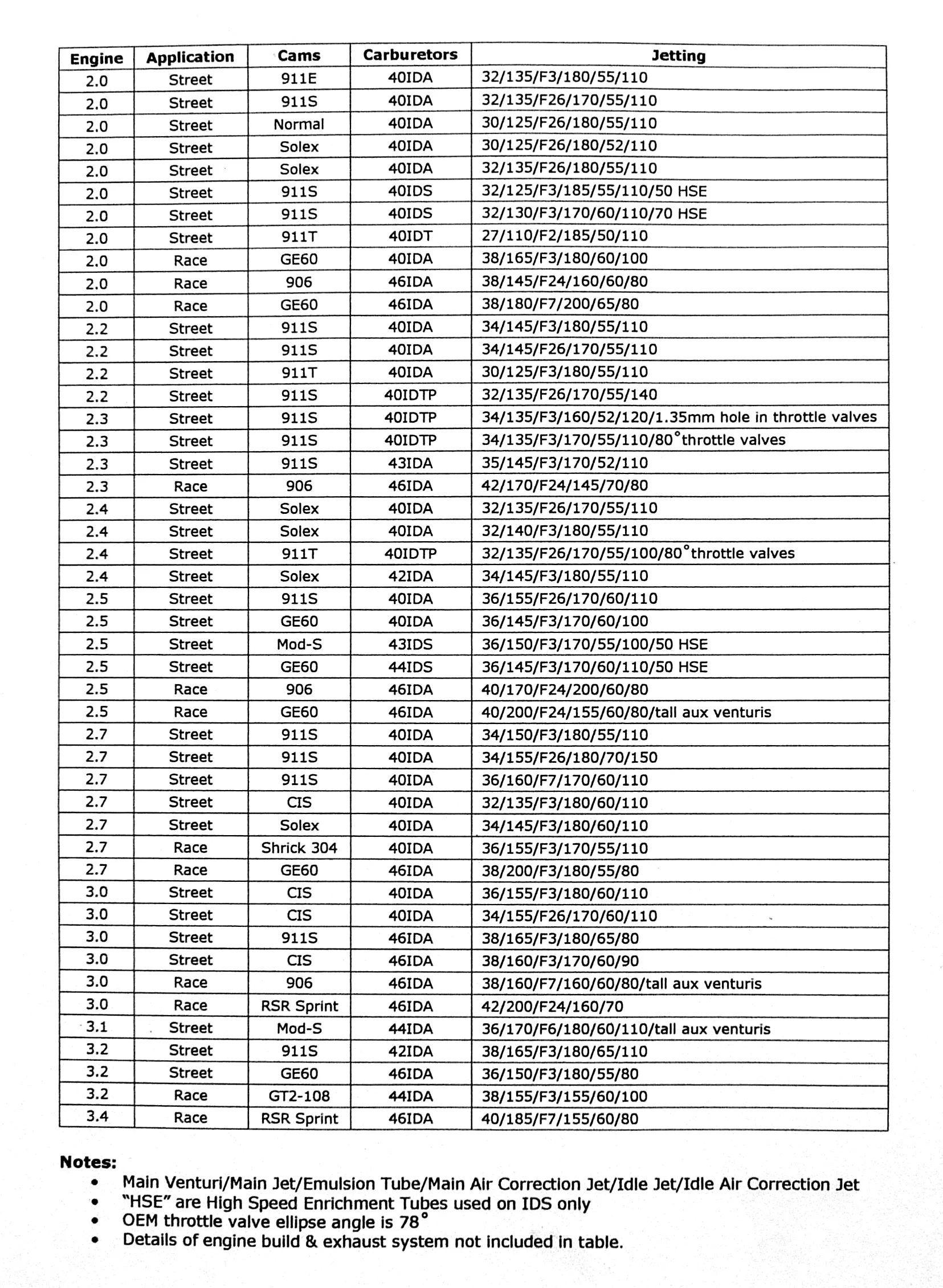
Main Jet Selection
Tuning the main circuit is rather straightforward and may be accomplished with a selection of jets and a series of road tests. In the process to select a main jet it is useful to use an idle jet that is slightly undersized (too lean) as this will help assure the main jet size supplies adequate fuel to help the second transition speed range and also helps to define when the main circuit becomes effective. If the engine runs “OK” above 3000 RPM but acts sluggish then it is probably too rich. Try dropping down on your main jet size and try driving again. It is good to optimize by repeating the decrease in main jet size until a definite lean situation has developed indicated by a subtle lean surge under part throttle while cruising at a steady 4000 RPM in 4th; increase the main jet sizeby "5" which should resolve the lean symptoms.
Once the main jets have been selected for engine speeds from 3000 to 5000 RPM the air correction jets are then selected for upper RPM usage. The air correction jets meter air, not fuel so larger means leaner fuel mixtures. The selection procedure is similar to that used for the main jets only at engine speeds above 5000 RPM. Test WOT operation through redline and at a steady cruise at 6000 RPM and check for stuttering or for going “flat”.” When it is clear that a lean stutter occurs then decrease the air corrector jet size until it disappears. Once you have selected your air correction jet it is prudent to select one that is one size smaller (by “10”) to protect your engine at sustained high speed.
After selection of the main jet and main air correction jet sizes from the above methods it is good to try other methods for verification of jetting suitability, remember that carburetors are tuned to be a "Best Fit" of jetting to various driving conditions. With any change of any jetting feature of your Webers there will be associated effects upon other regions of carburetor operation and jetting. Remember that carburetor jetting is an iterative process that requires patience and understanding of the various components and their interactions to achieve the optimum jetting package for any particular engine and application.
The following "Roll-Off Method" is an easy method to check the jetting of the main circuit:
With the engine fully warmed up, cruise at 3500 RPM in third or fourth (allows a little more time to evaluate the test response). Apply full throttle and allow engine to reach 5000 RPM (time enough to settle-in and for accelerator squirt to dissipate). Quickly Roll-Off the throttle to a 80% throttle open position. This will momentarily richen the fuel mixture. If the engine responds by gaining power and accelerating then this indicates a lean jetting configuration. If the engine goes flat, stutters or runs rough then the mixture is rich. Remember that the fuel delivery on the main circuit is the summation of fuel supplied by the main jet, the emulsion tube and the main air correction jet. The Roll-Off test provides an indication of jetting during a particular region of operation.
General Tuning Actions:
Lean fuel delivery conditions and actions to remedy:
- If RPM is below 2500 (progression circuit region of operation)
- Increase idle jet size
- Increase idle richness usingidle mixture screw
- If RPM is 2500 to 3000 RPM (upper progression region of operation)
- Decrease idle air bleed jet size
- If RPM is 2700 to 3500 RPM (transition region of operation)
- Select emulsion tube with emphasis on low RPM fuel delivery
- If RPM is 3200 to 5000 RPM (main circuit operation)
- Increase main jet size
- Select or modify emulsion tube to have fewer holes in middle portion of body
- If RPM is above 5000 RPM (upper main circuit region of operation)
- Decrease main air correction jet size
Note: For racing applications it is customary to use a smaller main air correction jet in conjunction with a larger main jet. This helps assure adequate mixture strength with little loss of power output.